coil condenser Heat Exchanger
coil condensers

download 74

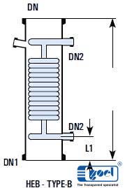
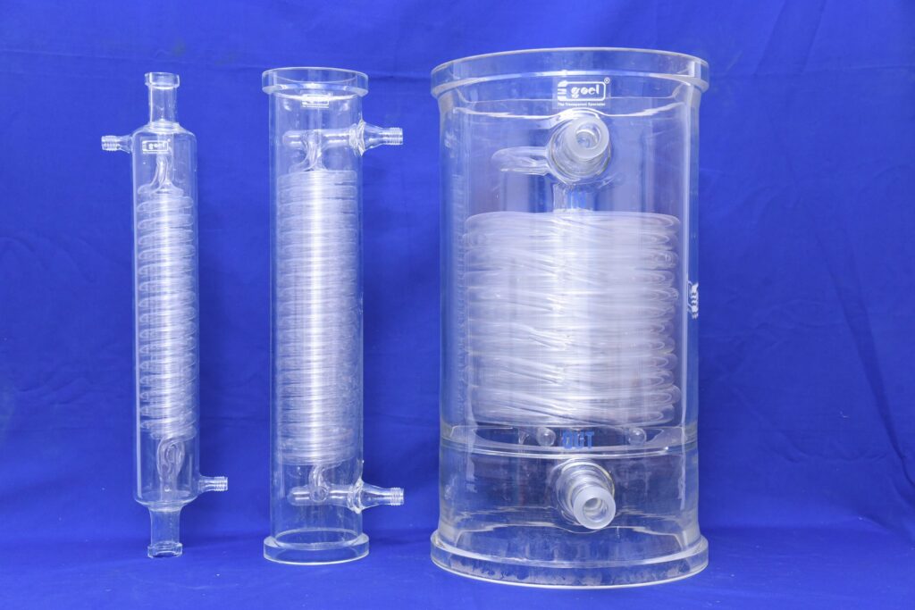
Coil Condensers are used for condensation of vapours and cooling of liquids. Condensers are made by fusing number of parallel coils in a glass shell. Coils are made in different diameters using tubes of different bores.

The average co-efficient of heat transfer in coil condenser is considered as :-
Condensation 200 – 270 Kcal/m2, hr, °C appx.
Cooling 100 – 150 Kcal/m2, hr, °C appx.
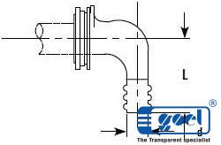

download 75

 Cat. Ref. DN d/DN1 L L1 Type Actual
H.T.A.
m2
Cross 
Area 
Cm2
Free
Coolant
Rate
kg/hr.
Max.
Jacket
Cap.
Litre
 HE3/3.5* 80 16 600 75 A 0.35 5 1300 2
 HE4/5* 100 19 600 75 A 0.50 30 2400 4
 HE4/6 100 19 750 100 A 0.60 30 2400 6
 HE6/10 150 25 600 100 B 1.00 52 2600 9
 HE6/15* 150 25 850 100 B 1.50 52 2600 11
 HE9/25* 225 25 800 110 B 2.50 125 3300 18
 HE12/25 300 25 600 125 B 2.50 175 5700 25
 HE12/40* 300 25 900 125 B 4.00 175 5700 35
 HE16/40 400 25 600 125 B 4.00 450 6200 60
 HE16/50 400 25 700 125 B 5.00 450 6200 70
 HE18/60 450 40 750 150 C 6.00 820 4800 100
 HE18/80 450 40 900 150 C 8.00 820 6200 110
 HE24/120 600 50 1250 300 C 12.00 1520 6200 265

Precautions to be taken in use of coil condensers :
– Vapours should be passed through shell only.
– Maximum pressure of coolant should be 2.7 bars.
– Adequate flow of coolant should be used.
– Steam should not be used in coils.
– Coolant should not be heated to boiling point.
– Coolant control valve should be turned slowly.
– Coolant should be allowed to drain freely.
– Brine can be used in coils in a closed circuit.
– Water main should be connected with flexible hose.
– Ensure no freezing of water remaining in the coils.
– Condensers should be mounted vertically only.
– Condensers can be mounted in series to provide larger surface area.

Methods of Use of Coil Condenser :

download 91

Vapours from bottom
This method is simple to install over a reactor. However this results in condensate returning substantially at its condensing temperature. In this method care must be taken that condensate is not excessive that it can lead to “logging” the coils and create back pressure in the system. Generally a reflux divider is used below the condenser to take out the distillate.

Vapors from top
This method produce a cool condensate using the entire coolinlg surface area. This method should be used where the condensate can lead to “logging” of coils.

BOILERS

Boilers are used for vaporization of liquids by passing the steam in the coils. Boilers are made by fusing number of parallel coils in a glass shell. In Boilers, coils are designed to provide bigger cross section in the shell side as compared to condensers. o The average heat transfer in Boilers is considered as 350 Kcal/m2,hr, C at a steam pressure of 3.5 bar.

 Cat.  Ref.
DN
DN1
DN2
L
L1
Type
Actual
H.T.A. m2
Free
Cross 
Area 
Cm2
Jacket Cap. Litre
 HEB4
100
25
25
375
100
A
0.15
40
2
 HEB4/4
100
100
25
400
100
B
0.15
40
3
 HEB6
150
40
25
450
100
A
0.35
50
5
 HEB6/6
150
150
25
500
100
B
0.35
50
7
 HEB9
225
40
25
700
100
A
1.00
150
16
 HEB9/9
225
255
25
700
100
B
1.00
180
20
 HEB12/12
300
300
25
700
125
B
1.30
330
40
download 93
download 92

Note on use of Boilers :
1. Steam should be passed in the coils at a maximum pressure of 3.5 bar which is equalant to a temperature of 147 °C.
2. For higher temperature (maximum upto 200 °C) heat transfer fluids can be passed in the coils. – Cold liquids
3. Cold liquids should be preheated for better results.
4. Boilers should bemounted in an external circulatory loop (as shown in figure) and not direct at the bottom of flask or column
5. Under certain circumstances, boilers can be mounted in series to provide larger heat transfer area.

ANGLED HOSE CONNECTOR ASSEMBLIES

Metal/Plastic angled hose connector assemblies are available to connect the flexible hose to the condensers. These are provide with a mating flange, a rubber gasket and nut bolts.

Cat.Ref.
DN
d
L
 PMC1
25
22
70
download 94

IMMERSION
Immersion heat exchangers are used to control exothermic reaction in glass vessels. They can be used with vessels having wider bottom outlet (type VSR and VSE). These are provided with a central hole through the coil battery so that a special, extended type, stirrer can be fitted which extends to the bottom of heat exchanger and provide through action.

In most applications, cooling water is used in coils (max. pressure 2.7 bar g.), but they can also be used with steam (max. pressure 3.5 bar g.). In latter case the coils must be completely immersed in liquid. Immersions are not recommended for use with products which have a tendency to crystalise.

download 95
Cat. Ref.
DN
DN1
DN2
L
L1
L2
d
Actual
H.T.A.
m2
 HEM6
150
40
25
200
200
75
145
0.4
 HEM9
225
40
25
300
200
75
200
0.6

PRODUCT COOLERS
Product coolers are used for cooling of liquids, typically, for the cooling of distillates from the distillation columns. Unlike coil condensers, in product coolers, product travels through the coil battery and coolant through shell. This provides more resident time to the product to be cooled. For direct connection with distillate lines, all the product coolers are provided with 25 DN connections.


download 97
Cat.Ref.
DN
DN1
DN2
L
Actual HTA 
m2
TYPE
 HEF1/1*
50
25
12
450
0.1
A
 HEF1/2*
50
25
12
600
0.2
A
 HEF1/3.5*
80
25
16
600
0.35
A
 HEF1/5*
100
25
19
600
0.5
A
 HEF1/10
150
25
25
600
0.7
B
 HEF1/15
150
25
25
850
1.25
B