




- GOEL Scientific
- October 14, 2026
- Pipeline Components
- 0 Comments
Picture transferring concentrated nitric acid, halogenated solvents or high-purity pharmaceutical media through a line without worrying about internal metal corrosion, line scaling or trace metal leaching. In chemical synthesis, API manufacturing and hazardous waste treatment, maintaining absolute fluid purity while managing aggressive reagents is an everyday operational demand. An industrial glass piping system replaces traditional metal alloys and plastic lines with transparent, chemically inert fluid paths. By selecting the right glass pipeline fittings and assembling them correctly, plant engineers achieve zero product contamination, full visual process control and long service life across demanding industrial lines.
Why Borosilicate 3.3 is Important for Industrial Glass Piping Systems
The reliable performance of an industrial glass piping system relies on the material properties of borosilicate 3.3 glass. Unlike standard metals or lined plastics, high-purity glass provides an impermeable, smooth surface that resists almost all aggressive chemicals.
- Universal Corrosion Resistance: Withstands concentrated acids, organic solvents and halogens (excluding hydrofluoric acid, hot phosphoric acid and strong caustics at high temperatures).
- Thermal Shock Tolerance: Features an extremely low coefficient of thermal expansion, allowing lines to manage rapid temperature shifts without cracking.
- Non-Porous Surface: Prevents chemical absorption, internal scaling and biofilm accumulation, lowering pressure drops and speeding up wash cycles.
- 100% Visual Clarity: Permits continuous monitoring of liquid flow rates, colour shifts, phase separation and air bubble formation inside glass pipeline components.
Classification of High-Performance Glass Pipeline Fittings
Constructing a leak-tight chemical network requires combining specialised glass pipeline fittings tailored to specific fluid transfer paths.
1. Primary Fittings: Bends, Tees and Reducers
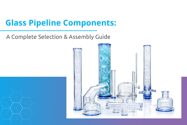
- Pipe Sections: Straight glass tubes with conical flanged ends, available in standard lengths to form main header lines.
- Bends (45° and 90°): Smoothly curved directional fittings designed to change fluid direction while minimising turbulence and internal wear.
- Tees (Equal and Unequal): Branch connectors that join side feeds, sample ports or instrument sensors into primary transfer runs.
- Reducers: Concentric or eccentric fittings that shift line sizes smoothly without creating stagnant pockets where fluid accumulates.
- Crosses and Spacers: Multi-port fittings used for complex fluid distribution and instrument spacing.
2. Secure Connections: Glass Pipe Connectors and Couplings
Joining fragile glass sections requires specialised glass pipe connectors that distribute mechanical clamping loads evenly across conical flanges. Standard coupling systems feature two outer metal backing flanges, an internal PTFE envelope gasket and stainless steel bolt sets. The PTFE insert rests between the glass faces, providing a soft, chemically inert seal that handles full vacuum and moderate pressure cycles without damaging the glass.
Key Selection Criteria for Glass Process Piping Components
Choosing the right glass process piping components requires matching fluid dynamics with mechanical equipment ratings.
| Operational Factor | Selection Requirement | Engineering Consideration |
| Operating Pressure | Full Vacuum up to 3.0 bar | Ratings decrease as nominal diameter (DN) increases. |
| Fluid Temperature | -50°C to +200°C | Ensure PTFE gaskets match operational thermal cycles. |
| Chemical Media | Concentrated acids & solvents | Verify gasket material compatibility for aggressive vapours. |
| Line Vibration | Thermal expansion joint inclusion | Install PTFE bellows near pumps or agitator connections. |
| Flow Volume | DN 15 up to DN 800 | Select correct nominal diameters to keep flow velocities optimal. |
Guide to Professional Glass Pipeline Installation
Proper glass pipeline installation requires precise alignment, structured support frames and careful bolt tightening sequences to eliminate mechanical stress on the glass flanges.
Proper Supporting and Alignment for Industrial Glass Piping
Unlike steel pipe networks, glass lines must never absorb structural building movements or support heavy external valves.
- Maintain Correct Hanger Spacing: Support horizontal glass runs every 1.5 to 2.0 meters using padded pipe inserts.
- Use Spring-Loaded Supports: Install spring hangers on vertical risers to absorb vertical thermal expansion smoothly.
- Prevent Rigid Anchoring: Allow pipeline sections to move axially within cushioned supports without binding.
- Isolate Heavy Equipment: Connect glass lines to pumps, metal reactors or heavy control valves using flexible PTFE bellows.
Assembly Best Practices: Tightening Glass Pipe Connectors
- Align the mating glass flanges so they sit parallel and centred before tightening any bolts.
- Insert the PTFE envelope gasket between clean, unmarred glass faces.
- Fit metal backing flanges over the cushioned glass shoulders.
- Hand-tighten all bolts to ensure the flanges seat evenly.
- Use a calibrated torque wrench to tighten bolts in a diagonal, cross-pattern sequence, applying incremental torque to avoid uneven stress points on the glass.
When assembling heavy-duty industrial lines, engineering teams depend on precision-manufactured glass process piping components. Goel Scientific Glass Works Ltd. fabricates a wide range of borosilicate 3.3 pipeline components, including straight pipe runs, bends, tees, jacketed lines and specialised glass pipe connectors. Designed to operate under full vacuum conditions, these modular components span nominal diameters from DN 15 up to DN 800 (with DN 1000 available on request). Incorporating Goel Scientific’s precision-ground fittings into your plant layout ensures low pressure drops, easy cleaning and reliable performance across chemical, pharmaceutical and precious metal refining lines.
Maintenance & Safety of Glass Process Piping Components
Regular inspection preserves operational integrity and prevents unexpected downtime in processing plants.
- Routine Flange Inspections: Periodically inspect PTFE gaskets for cold flow deformation or chemical weeping, especially after initial thermal cycles.
- Check for Physical Defects: Inspect glass surfaces for deep scratches, impact chips or internal etching caused by hot alkaline solutions.
- Inspect Support Hardware: Verify that pipe supports remain cushioned and free-floating, without rust or rigid binding against the glass body.
- Implement Safe Line Bleeding: Always drain and depressurise glass piping completely before loosening backing flange bolts during routine maintenance.
Conclusion
Building a reliable, leak-free industrial glass piping system requires proper material selection, correct support structures and precise bolt-torque management. By using high-grade borosilicate 3.3 pipeline components and following recommended installation practices, facilities gain complete process visibility, absolute chemical purity and long-term operating safety. Upgrading to engineered glass pipeline systems eliminates product contamination risks and protects your processing lines for years of continuous service.
FAQs
Use a specialised metal-to-glass adaptor flange fitted with a PTFE envelope gasket and flexible PTFE bellows. The bellows isolates the glass line from mechanical vibrations, thermal expansion forces and structural loads generated by the metal piping system.
Borosilicate 3.3 glass handles operating temperatures up to +200°C (and thermal shocks up to 120°C differential). Pressure ratings depend on line size, ranging from 3.0 bar for small diameters (DN 15-25) to 0.5 bar/full vacuum for large industrial lines (DN 600-800).
Uneven bolt tightening concentrates stress on specific points of the glass flange, causing it to chip or shatter. Using a diagonal cross-pattern with a calibrated torque wrench applies uniform clamping force across the PTFE gasket, creating a leak-free seal without damaging the glass.
Yes, high-grade borosilicate glass pipeline components and PTFE envelope gaskets are engineered to maintain tight seals under full vacuum conditions, making them suitable for vacuum distillations, solvent recovery and low-pressure chemical transfers.
Replace any component that shows star cracks, deep surface scratches, severe internal chemical etching or chipped flange faces. Damaged glass sections under pressure or thermal cycling pose safety risks and should be replaced immediately during routine maintenance shutdowns.
